*Modeling a sequential machine: 3 approaches
*Modeling a sequential machine: 1) Behavioral modeling - ex.1
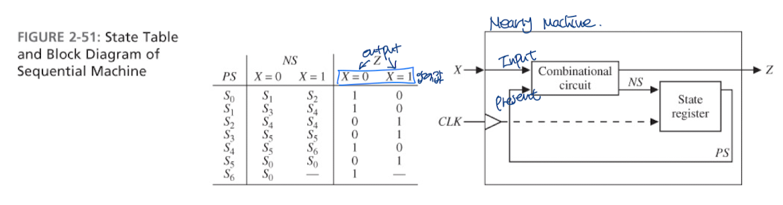
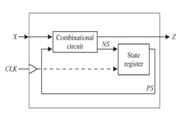
//This is a behavioral model of Mealy state machine(Figure 2-51)based on its state table.
//The output(Z) and next state are computed before the active edge of the clock.
//The state change occurs on the rising edge of the clock.
module Code_Converter(X, CLK, Z);

input X, CLK, Reset;
output Z;

reg Z;
reg [2:0]State;
reg [2:0]Nextstate;

initial
begin
	State = 0;
    Nextstate = 0;
end

always@(State or X) //Combinational circuit
begin
case(State)
	0 : begin
    		if(X == 1'b0);
       		begin
        		Z = 1'b1;
            	Nextstate = 1;
        	end
        	else
        	begin
        		Z = 1'b0;
            	Nextstate = 2;
            end
        end
    1 : begin
    		if(X == 1'b0);
        	begin
            	Z = 1'b1;
                Nextstate = 3;
            end
            else
            begin
            	Z = 1'b0;
                Nextstate = 4;
            end
        end
    2 : begin
    		if(X == 1'b0);
        	begin
            	Z = 1'b0;
                Nextstate = 4;
            end
            else
            begin
            	Z = 1'b1;
                Nextstate = 4;
            end
        end
    3 : begin
    		if(X == 1'b0);
        	begin
            	Z = 1'b0;
                Nextstate = 5;
            end
            else
            begin
            	Z = 1'b1;
                Nextstate = 5;
            end
        end
    4 : begin
    		if(X == 1'b0);
        	begin
            	Z = 1'b1;
                Nextstate = 5;
            end
            else
            begin
            	Z = 1'b0;
                Nextstate = 6;
            end
        end
    5 : begin
    		if(X == 1'b0);
        	begin
            	Z = 1'b0;
                Nextstate = 0;
            end
            else
            begin
            	Z = 1'b0;
                Nextstate = 0;
            end
        end
    6 : begin
    		if(X == 1'b0);
        	begin
            	Z = 1'b1;
                Nextstate = 0;
            end
            else
            begin
            	Z = 1'b0;
                Nextstate = 0;
            end
        end
    default : begin
    end
    endcase
end

always@(posedge CLK) //State Register
begin
	if(Reset)
    	State <= 3'b000;
    else
	State <= Nextstate;
end

endmodule
코드를 보고 Simulator그리기
*Modeling a sequential machine: 1) Behavioral modeling - ex.2
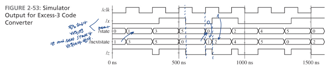
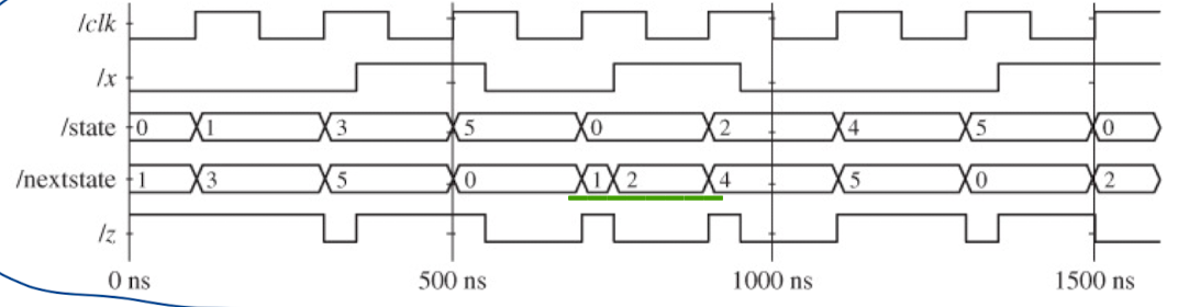
Simulator를 보고 밑 코드 설계
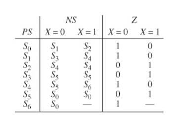
//This is a behavioral model of the Mealy state machine for BCD
//to Excess-3 Code Converter based on its state table.
//The state change occurs on the rising edge of the clock.
//The output is computed by a conditional assignment statement
//whenever State or Z changes.
module Code_Converter(X, CLK, Z);
input X, CLK;
output Z;
wire Z;
reg [2:0]State;
initial
begin
State = 0;
end
always@(posedge CLK) //Sequential logic
begin
case(State)
0 : begin
if(X == 1'b0)
State <= 1;
else
State <= 2;
end
1 : begin
if(X == 1'b0)
State <= 3;
else
State <= 4;
end
2 :
State <= 4;
3 :
State <= 5;
4 : begin
if(X == 1'b0)
State <= 5;
else
State <= 6;
end
5 :
State <= 0
6 :
State <= 0;
default : begin
end
endcase
end
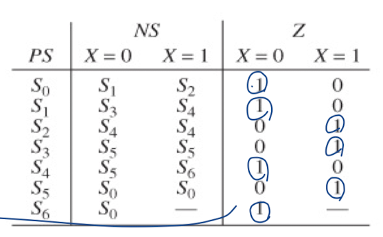
//표를 보고 Z에 1되는 경우와 연결시킨다.
assign Z = ((State == 0 && X == 1'b0) || (State == 1 && X == 1'b0) || (State == 2 && X == 1'b1)
|| (State == 3 && X == 1'b1) || (State == 4 && X == 1'b0) || (State == 5 && X == 1'b1)
|| (State == 6 && X == 1'b0)) ? 1'b1 : 1'b0;
endmoduleQ. case 0에서 posedge인데 nextstate 1,2로 갈리는 것을 어떻게 나타내는지?
*Modeling a sequential machine: 2) Data Flow(RTL) modeling
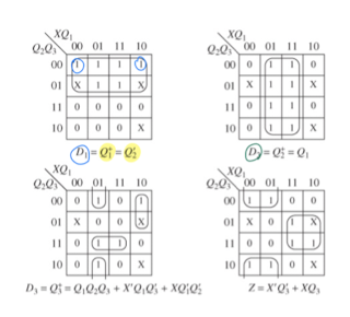
위의 Karnaugh map을 보고 코드 설계
//The following is a description of the sequential machine of the BCD
//to Excess-3 code converter in terms of its next state
//equations obtained as in Figure 1-25.
//The follwing state assignment was used
//: S0-->0; S1-->4; S2-->5; S3-->7; S4-->6; S5-->3; S6-->2;
module Code_Converter(X, CLK, Z);
input X;
input CLK;
input Z;
reg Q1;
reg Q2;
reg Q3;
//wire Z;
always@(posedge CLK)
begin //3 Clock뒤에 +3 출력이 나온다
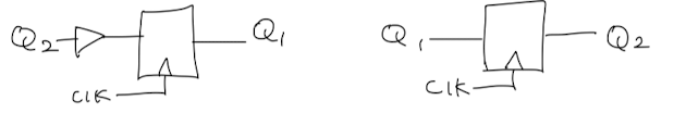
Q1 <= #10 (~Q2);
Q2 <= #10 Q1;
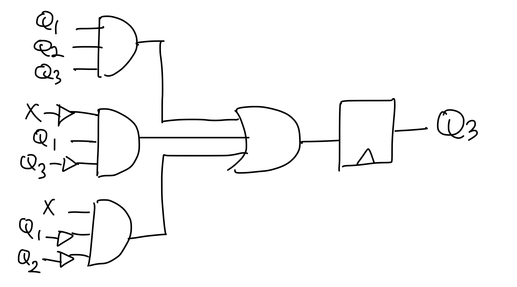
Q3 <= #10 (Q1 & Q2 & Q3) | ((~X) & Q1 & (~Q3)) | (X & (~Q1) & (~Q2));
end
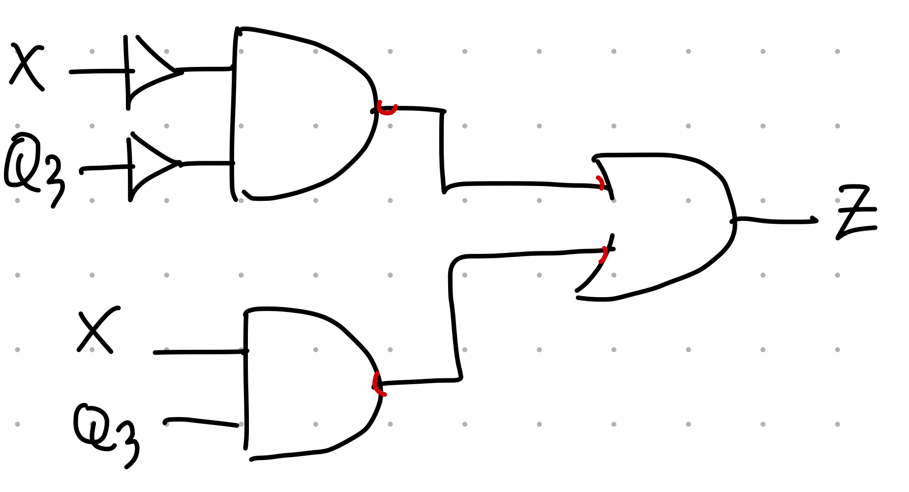
assign #20 Z = ((~X) & (~Q3)) | (X & Q3);
endmodule
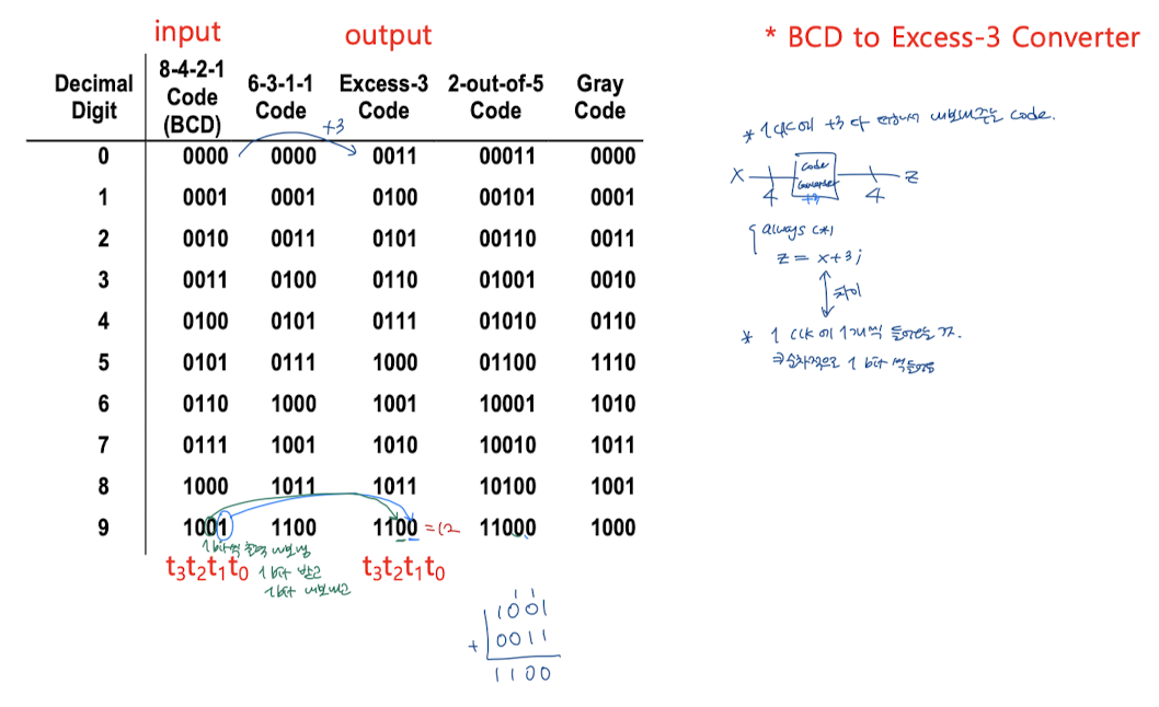
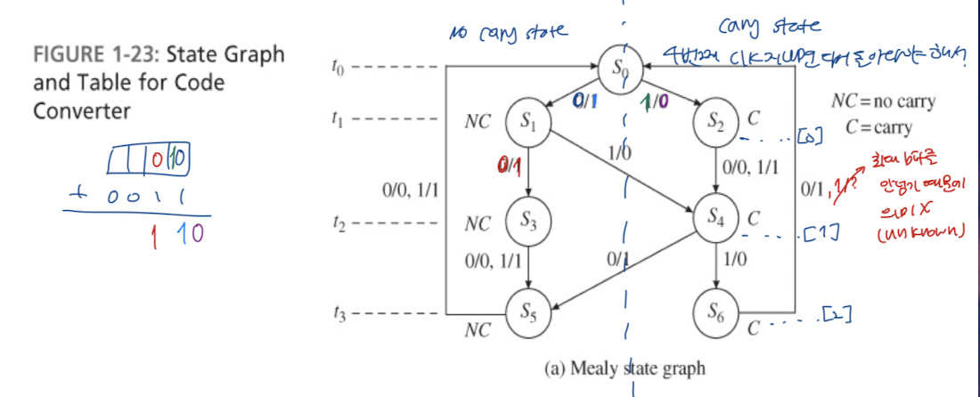
- +3해주는 code라서 +0011과 input(X)값을 하나씩 비교해서 나오는 output(Z)값이 정답값(slash 오른쪽에 있는 값)이다.
: 출력을 모으면 output = 정답 값이 된다.
=> state graph로 입력을 넣은 값과 출력 값을 알 수 있다.
*Modeling a sequential machine: 3) Gate-Level modeling
// D Flip-Flop
module DFF(D, CLK, Q, QN);
input D;
input CLK;
output Q;
output QN;

reg Q;
reg QN;

initial
begin
    Q = 1'b0;
    QN = 1'b1;
end

always@(posedge CLK)
begin
	Q <= #10 D;
    QN <= #10 (~D);
end

endmodule
// 3 input NAND gate
module Nand3(A1, A2, A3, Z);
input A1;
input A2;
input A3;
output Z;
assign #10 Z = (~(A1 & A2 & A3));
endmodule
Q1 <= #10 (~Q2);
Q2 <= #10 Q1;
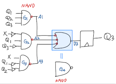
Q3 <= #10 (Q1 & Q2 & Q3) | ((~X) & Q1 & (~Q3)) | (X & (~Q1) & (~Q2)); //Nand3로 변환
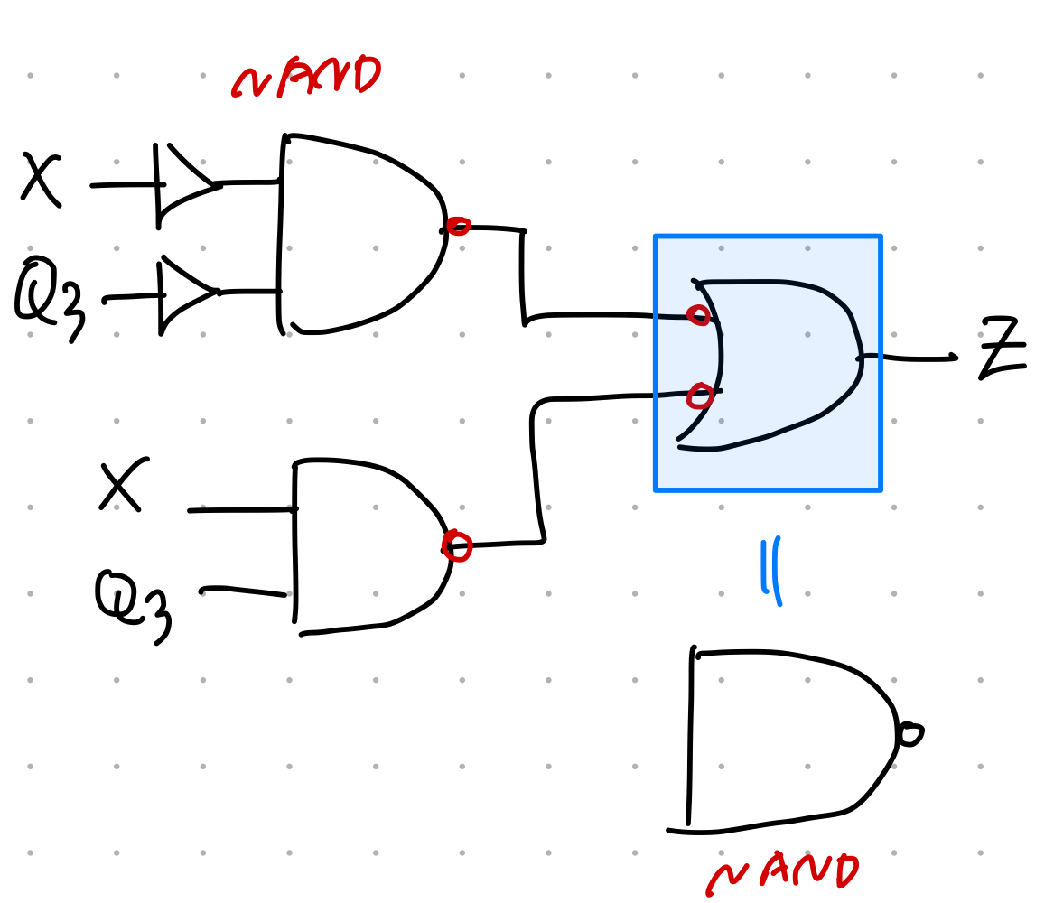
Z = ((~X) & (~Q3)) | (X & Q3); //Nand2로 변환위 block을 아래 Nand로 모두 변환
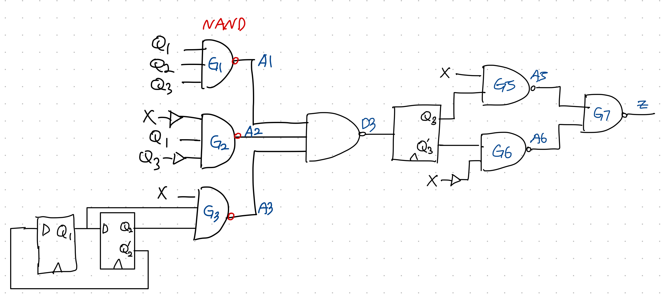
//The follwing is a STRUCTURAL verilog description of
//the circuit to realize the BCD to Excess-3 code Converter.
//This circuit was illustrated in Figure 1-26.
//Uses cmoponents NAND3, NAND2, INVERTER and DFF
//The component modules can be included in the same file
//or they can be inserted as separate files.
module Code_Converter(X, CLK, Z);
input X, CLK;
output Z;
wire X, CLK, Z, A1, A2, A3, A4, A5, A6, D3, Q1, Q2, Q3, Q1N, Q2N, Q3N, XN;

Inverter I1(X, XN);

Nand3 G1(Q1, Q2, Q3, A1);
Nand3 G2(Q1, Q3N, XN, A2);
Nand3 G3(X, Q1N, Q2N, A3);
Nand3 G4(A1, A2, A3, D3);

DFF FF1(Q2N, CLK, Q1, Q1N);
DFF FF1(Q1, CLK, Q2, Q2N);
DFF FF1(D3, CLK, Q3, Q3N);

Nand2 G5(X, Q3, A5);
Nand2 G6(XN, Q3N, A6);
Nand2 G7(A5, A6, Z);

endmodule
최종 block???(예상)
'Study > Digital System Design and Lab[Verilog]' 카테고리의 다른 글
| #6-1 Sequential Circuit Design - Finite State Machine (Mealy-circuit) (1) | 2023.10.17 |
|---|---|
| #5 Finite State Machine - Moore, Mealy Machine (0) | 2023.10.15 |
| #5-1 Sequential Circuit Design - Finite State Machine (Moore-circuit) (0) | 2023.10.15 |
| #4-1 "IF", "Case" Statement - Counter (1) | 2023.10.15 |
| #3-2 Shift Register (0) | 2023.10.15 |