* "If", "Case" Statement
- An if statement has the form:
if (condition)
	statements 1
else if (condition)
	statements 2
...
else
statements 3- A Case Statement has the form:
case expression
	choice1 : statements1
    choice2 : statements2
    ...
    [default : statements5]
endcase
*Verilog Models for Multiplexers
- A multiplexer is a conbinational circuit and can be modeled using:
- A conditional operator with assign statement.
- A case statement or if-else statement. - A conditional signal assignment statement has the form:
assign signal_name = condition ? expression_T : expression_F;

if(E)
	F = A;
else if(0)
	F = B;
else
	F = C;
case ({D, E}) //2bit
2'b00 : F = C;
2'b01 : F = A;
2'b10 : F = b;
2'b11 : F = A;
default : F = 0;
endcase
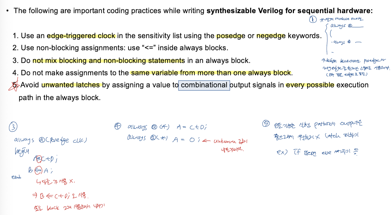
- Important coding practices while writing synthesizable Verilog for combinational hardware:
1. If possible, use concurrent assignments (e.g., assign) to design combinational logic.
2. When procedural assignments (always blocks) are used for combinational logic, use blocking assignments(=).
2. If Verilog 2001 or later is used, instead of specifying contents of sensitivity lists, use always@(*) to avoid accidental omission of signals from sensitivity lists.
*Modeling Registers/Counters Using Verilog Always Statements
- 몇몇 flip-flops가 같은 clock edge에 state를 바꿀 때, 이 FF를 나타내는 statement들은 같은 clock always statements에서 동작할 수 있다.
- 위의 FF는 rising edge에서 상태가 바뀌고 세개의 always statement는 동시에 수행된다.
- delay(#5)를 제거하고 동작시켜도 같다. 왜냐하면 합성엔 delay가 안들어가기 때문이다.
- non-blcking assignment operator(<=)를 사용할 때 statement의 순서는 중요하지 않다.
어차피 동시에 수행되기 때문에 순서가 바뀌어도 같은 결과가 나온다. - Single flip-flop
module reg31 (Q1, Q2, Q3, A, CLK); //Reset추가필요
input A;
input CLK;
output Q1, Q2, Q3;
reg Q1, Q2, Q3;
always @(posedge CLK) //sequential logic
begin
//if Reset else 넣어주기
	Q1 = A; //statement 1
    Q2 = Q1; //statement 2
    Q3 = Q2; //statement 3
end
endmodule- if-else로 초기 Reset값 넣어주면 좋다
- sequential logic인데 blocking block(=)을 사용했기에 순차적으로 statement가 바뀌기 때문에
Q3 = A의 값을 가진다.
=> 1 CLK 만에 Q3로 전해진다.
- Flip-flops(Refisters)
module reg31 (Q1, Q2, Q3, Reset, A, CLK); //Reset추가
input A;
input CLK;
output Q1, Q2, Q3;
reg Q1, Q2, Q3;
always @(posedge CLK) //sequential logic
begin
	if (Reset)
		Q1, Q2, Q3, Q4 <= 4'b0000; //initial
	else
		Q1 <= A; //statement 1
  	  	Q2 <= Q1; //statement 2
  	  	Q3 <= Q2; //statement 3
end

endmodule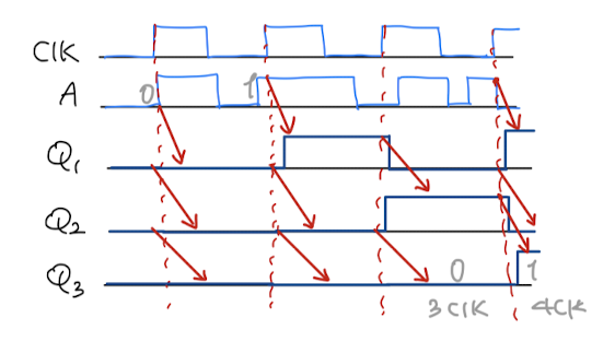
=> 3 CLK만에 Q3로 전해진다.
- Avoiding unwnated latches:
- Verilog signals retain their current values until they are changed.
This can result in the creation of unwanted latches when the Verilog code is synthesized.
For example:
always@(Sel or I0 or I1 or I2) begin //combinational logic
	if (Sel == 2'b00) F = I0;
    else if (Sel == 2'b01) F = I1;
    else if (Sel ==2'b10) F = I2;
end
- This code was written intending a MUX.
- latch를 발생시킨다.
: else가 없는 것! else를 안쓰려면 initialize F = 0;을 처음에 써주어야 한다.
//수정코드
always@(Sel or I0 or I1 or I2) begin //combinational logic
	//initial F = 0
    if (Sel == 2'b00) F = I0;
    else if (Sel == 2'b01) F = I1;
    else if (Sel ==2'b10) F = I2;
    else F = 0; //F = F;는 불가능 : 값을 저장하는 logic이 아니라서
end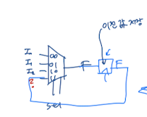
Flip-flop을 사용해서 값을 저장해서 사용하려면 sequential logic을 사용한다.
always@(posedge CLK) //sequential logic
begin
	if (Sel == 2'b00) F <= I0;
    else if (Sel == 2'b01) F <= I1;
    else if (Sel ==2'b10) F <= I2;
    else F <= F;
end
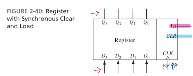
always@(posedge CLK)
begin
	if (CLK) Q <= 4'b0000; //Reset
    else if (Ld) Q <= D;
	//else Q <= Q; sequential logic에서는 else를 생략 해도된다.
end
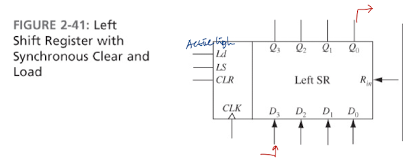
always@(posedge CLK)
begin
	if (CLR) Q <= 4'b0000;
    else if (Ld) Q <= D;
    else if (LS) Q <= {Q[2:0], Rin};
end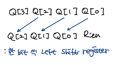

위 Counter사용해서 밑에 logic설계
//Counter Model
module c74163(LdN, ClrN, P, T, Clk, D, Cout, Qout);
intput LdN, ClrN, P, T, Clk;
input [3:0]D;
output Cout;
output [3:0]Qout;

reg[3:0] Q;

assign Qout = Q;
assign Cout = Q[3] & Q[2] & Q[1] & Q[0] & T;
//Q모두가 1일 때 더이상 저장 불가능하니 앞에 1bit올려주고 나머지는 0으로 reset하기 위함
//다음 단의 T로 들어가는 Cout이다.

always@(posedge Clk)
begin
	if(~ClrN) Q <= 4'b0000;
    else if (~LdN) Q <= D;
    eles if (P & T) Q <= Q + 1;
    //else Q <= Q 생략
end

endmodule
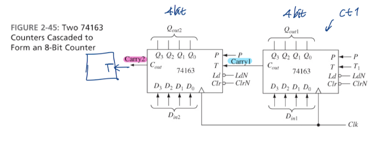
//8-Bit counter usint two 74163 counters using the model in Fig 2-44
module eight_bit_counter(ClrN, LdN, P, T1, Clk, Din1, Din2, Cout, Carryy2);
input ClrN, LdN, P, T1, Clk;
input [3:0] Din1;
input [3:0] Din2;
output [7:0] Count;
output carry2;

wire carry1;
wire [3:0] Qout1;
wire [3:0] Qout2;

c74163 ct1(LdN, ClrN, P, T1, Clk, Din1, Carry1, Qout1); //instance1 (right)
c74163 ct1(LdN, ClrN, P, Carry1, Clk, Din2, Carry2, Qout2); //instance1 (right)

assign Count = {Qout1, Qout2};

endmodule'Study > Digital System Design and Lab[Verilog]' 카테고리의 다른 글
| #3-2 Shift Register (0) | 2023.10.15 |
|---|---|
| #3-1 D Flip-Flop (0) | 2023.10.15 |
| #4 Simple Synthesis Examples (0) | 2023.10.15 |
| #3 Modeling Flip-Flops Using Always Block (0) | 2023.10.14 |
| #2-2 Multiplexer Design (0) | 2023.10.11 |